General Description
 The
Radar Printer Interface took data from either a WF44 radar or a WF3 radar Raprint
unit and drove a parallel printer. It calculated the wind data only if the radar
output was is in the correct format otherwise the unit would send only the raw
data as received to the printer, without any calculations included. In that
way if there was any faults in the radar that were causing erroneous readings,
the observer could review the data and manually estimate the winds. Both station
height and earth curvature were included in the wind calculations.
The
Radar Printer Interface took data from either a WF44 radar or a WF3 radar Raprint
unit and drove a parallel printer. It calculated the wind data only if the radar
output was is in the correct format otherwise the unit would send only the raw
data as received to the printer, without any calculations included. In that
way if there was any faults in the radar that were causing erroneous readings,
the observer could review the data and manually estimate the winds. Both station
height and earth curvature were included in the wind calculations.
Deployment
The Interface was used on the following WF44 and WF3 radars
Camp Rd WF44
Canberra WF3
Darwin WF44
Laverton WF44
Mascot WF3
*Perth (EPA) WF44
Launceston WF3
Tennant Creek WF3
All of the units on WF44 radars were removed in the late 1990's when they were
upgraded with the introduction of PC Radwin.
* Changed from a Radar Printer Driver in 1992 for use in an EPA experiment on
the Perth WF44 radar.
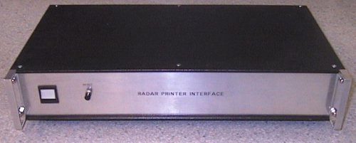
Construction
About nine of these units were built in Radar Section in the mid 1980's. As
can be seen above the sheet metal chassis had a black plastic ripple finish
and was 430 x 220 x 75mm. It was placed beside the radar console often with
the dot matrix printer resting on top. The interface was based on an imported
Z80 processor card (the MCB 80). Purchased as an unloaded circuit card, all
the components were purchased and loaded in Australia. A DB9 female connector
was used for the input data, a DB15 connector for the printer connection and
the serial data was available from a DB25 socket.
Operation
The unit was switched on when a windflight was about to be performed and then
on pressing the front panel RESET switch the printer would print the header
lines.
For example
Mascot WF3 Station Height = 5m
C TIME RANGE AZIM ELEV HGHT SP DIR
This indicates the station name - Mascot WF3 and the official station height.
The second line forms the headings for the printout columns.
SAMPLE PRINTOUT
|
Mascot WF3 Station Height = 5m |
|||||||
| C |
TIME
|
RANGE
|
AZIM
|
ELEV
|
HGHT
|
SP
|
DIR
|
|
205 |
01.0 |
000.44 |
257.0 |
35.8 |
262 |
6 |
257 |
|
205 |
02.0 |
000.85 |
262.0 |
34.3 |
484 |
6 |
267 |
|
205 |
03.0 |
001.36 |
263.1 |
32.7 |
740 |
7 |
265 |
|
205 |
04.0 |
001.88 |
262.7 |
34.8 |
1078 |
7 |
262 |
|
205 |
05.0 |
002.42 |
265.0 |
35.2 |
1400 |
7 |
273 |
|
205 |
06.0 |
003.04 |
261.8 |
34.4 |
1723 |
9 |
250 |
|
205 |
07.0 |
003.73 |
259.8 |
33.3 |
2054 |
10 |
252 |
|
205 |
08.0 |
004.58 |
260.4 |
31.5 |
2399 |
13 |
263 |
|
205 |
09.0 |
005.37 |
262.2 |
30.5 |
2732 |
12 |
272 |
|
205 |
10.0 |
006.05 |
263.4 |
30.5 |
3077 |
10 |
273 |
|
205 |
11.0 |
006.74 |
264.4 |
30.4 |
3418 |
10 |
273 |
|
205 |
12.0 |
007.55 |
265.7 |
30.0 |
3783 |
12 |
276 |
|
205 |
13.0 |
008.42 |
265.7 |
29.5 |
|
|
|
|
205 |
14.0 |
009.34 |
266.2 |
28.8 |
4509 |
14 |
268 |
|
205 |
15.0 |
010.40 |
267.7 |
27.8 |
|
|
|
|
205 |
16.0 |
011.55 |
267.4 |
26.7 |
5202 |
18 |
272 |
|
205 |
17.0 |
012.71 |
267.1 |
25.9 |
|
|
|
|
205 |
18.0 |
013.79 |
267.3 |
25.3 |
5909 |
18 |
267 |
|
205 |
19.0 |
014.91 |
266.8 |
24.8 |
|
|
|
|
205 |
20.0 |
016.01 |
266.7 |
24.4 |
6633 |
18 |
263 |
|
205 |
21.0 |
017.11 |
266.6 |
23.7 |
|
|
|
|
205 |
22.0 |
018.31 |
266.4 |
23.2 |
7237 |
19 |
264 |
|
205 |
23.0 |
019.49 |
266.8 |
22.8 |
|
|
|
|
205 |
24.0 |
020.72 |
267.2 |
22.1 |
7825 |
20 |
273 |
|
205 |
25.0 |
022.08 |
267.2 |
21.5 |
|
|
|
|
205 |
26.0 |
023.50 |
268.2 |
20.9 |
8421 |
23 |
275 |
The first column 'C' is the CODE. This was sent from the radar to indicate
which mode it was in
0 - Visual Control
1 - Manual Control
2 - Steer Mode
3 - Auto Follow
The next two digits came from thumbwheel switch settings on the radar console
and were set as desired by the observer.
Once the 12th minute had passed the unit then only calculated the winds every two minutes.
The Serial Output
This serial output was not calculated data, only raw data. It was not used for
driving a printer but for recording flight data on another device for miscellaneous
projects. In once such case(1992), the data from the Perth Airport radar was
logged by a Personal Computer for the Environment Protection Agency.