Technical details
General Description
 The
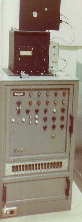
Photo PPI (manufactured as Photographic Repeater Scope by E.E.C.) had a 7 inch
C.R.T. to provide a Plan Position Indicator set in the top of the cabinet. Over
this, mounted on top of a light-proof box, was a 16mm movie camera. It was a
self contained unit that required 115vac from a large transformer, 2.5v peak
video, trigger and azimuth synchro information. Displayed ranges were; 128,
230 and 450km with 20, 50, and 100-km range rings respectively.
The
Photo PPI (manufactured as Photographic Repeater Scope by E.E.C.) had a 7 inch
C.R.T. to provide a Plan Position Indicator set in the top of the cabinet. Over
this, mounted on top of a light-proof box, was a 16mm movie camera. It was a
self contained unit that required 115vac from a large transformer, 2.5v peak
video, trigger and azimuth synchro information. Displayed ranges were; 128,
230 and 450km with 20, 50, and 100-km range rings respectively.
The CRT had a perspex bearing ring that was edge lit by small incandescent lamps whose intensity was adjustable for the correct exposure. A series of six LED readouts provided ancillary data such as image exposure number, date, time, elevation angle, and a code for the type of video being displayed. A backlit perspex panel with the station name engraved also provided a small area for one or two words to be inscribed using a chinagraph pencil. Often this would be used to indicate a cyclone name if relevant.
The unit utilized both TTL and transistor technology with the
only valve being the 7ABP7 CRT. Many of the cards were wire-wrap. It had a 6v
9.5AH sealed lead acid battery for day/date clock backup.The final camera motor
drive electronics made by Lafayette was mounted on the side of the light-proof
box.
The automatic exposure process was triggered from a combination of the internal
timer and the radar's North Marker. In the late 80's a Photo PPI Controller
card was added to allow control of the system from an external signal from a
Rapic Transmitter.
Cameras supplied:
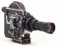 Bolex
H16-SBM with 100' magazine for 16mm movie film (Pictured)
Bolex
H16-SBM with 100' magazine for 16mm movie film (Pictured)
Polaroid type 88-1 (CU5-4x5) as backup & test
The 100 foot length of film would last four days at a frame exposure rate of
one every 2 minutes on the photo PPI..
WF44 Code Interface Unit
Used for interfacing to the WF44 radars signals this signal PCB housed in a
die-cast box (often hidden under floor or plinth) connected the Photo PPI to
the radar console, used TTL logic to convert status information to provide the
LED code.