Technical details
General Description
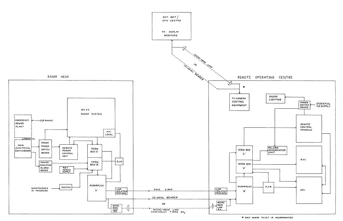
Radarplex may be sub-divided into the following individual systems:
Apart from the specialised interfacing arrangements involved,
the Command and Tellback systems were functionally identical with the Bureau-developed
"Teleplex" equipment used at a number of locations for meteorological telemetry.
They were approved for connection to private telephone lines under Telecom permits.
Spare capacity in the Command and Tellback links was used in such "house -keeping"
applications as fire alarm indications and control and monitoring of emergency
power generation equipment.
An overall block diagram of the Radarplex Remoting System
WF44 Modifications
Three significant modification was all that was required to a standard WF44
radar system to allow remote operation by Radarplex:
The WF44 Transmitter trigger unit was modified slightly to allow its internal
repetition-rate generator to be externally synchronised, -when in weather watch,
to a 250 Hz signal derived from the Radarplex Video Transmitter.
The radarplex system energised the azimuth and elevation antenna resolvers with
its own internally generated reference waveform from which DC sine and cosine
signals are derived for the PPI and RHI units.
The Remote Control Console was programmed for Radarplex use by fitting an appropriate
link plug on its rear panel.
Construction
Wire-wraping the card frames for the system was contracted to two companies.
One was Zephur Products, in Mt Waverley a suburb of Melbourne and the other
was in Sydney.(2) The story is told that this
Sydney company employed illegal Spanish migrants!
References
(1) EH355 RADARPLEX Technical Handbook
(2) Chris Heal (private communication
2002)