Technical details
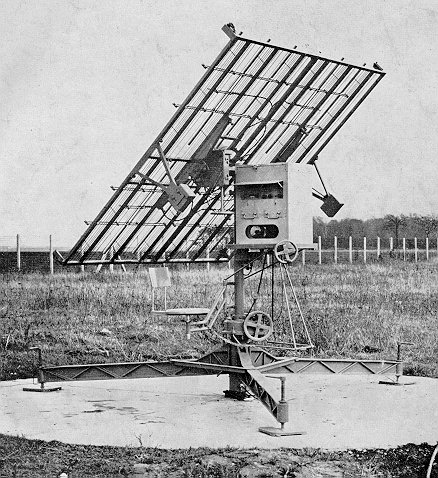
| AERIAL |
|
32 half wavelength elements arranged in 4 bays |
| RECEIVER |
| 390 - 407MHz |
| DISPLAY |
| 5 inch diameter P1 phosphor CRT, viewed via a mirror, displaying 4 vertical pips to indicate received signal strength from each antenna bay |
| READOUTS |
|
Mechanically driven dial indicators with |
| OTHER EQUIPMENT |
Receiver:
comprising-
RF amplifier, mixer, oscillator and two 19MHz stages of IF amplification feeding
two channels.
Channel 1(FM channel)
Has three stages of IF amplification before discriminating the FM signals for the remote radiosonde chart recorder.
Channel 2(AM channel)
The IF is modulated by the antenna switch prior to amplification and detection for feeding the CRT for direction finding on the received signal.
CRT Display(type 'K' presentation)
Vertical Deflection
Four signals corresponding to each received antenna lobe are displayed with their vertical amplitude proportional to the signal strength received in each lobe.
Horizontal Sweep
The sweep is initiated twice for each revolution of the motor-driven antenna switch. A spread control causes the second sweep to be displaced horizontally causing the display to show four vertical pips across the CRT, each representing one antenna lobe position.Aerial Switch problems
The aerial switch suffered greatly from water ingress as well as electro-mechanical failure. The Central Workshop averaged more than six overhauls of these switch assemblies per year in the 60's. Unit were lasting only about ten months in service before requiring replacement.(3)Hence some effort was required to try to reduce these failures. Hence the Bureau's specification for the aerial switch contacts bothered to emphasise to the sub-contractors that each contact would flex approximately 46 million times for each 12 months of operation!(2)
The repair process was thus:
Motor rewound by contractor, contacts cleaned and reset, oiled and cover gasket replaced by Workshop in Hoddle St Collingwood Vic. Then the assembly was tested by the Radio Lab at Bowes Ave Essendon before being returned to Workshops for sealing and painting prior to issue.(3)
Handbook Photo of Metox installation without canvas tent
(1) Metox Radiotheodite Technical Manual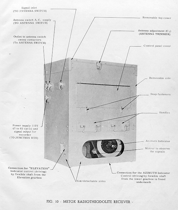