Technical details

The WF3 radar was developed by Plessey after taking over Decca operation.(1)
The PRF was developed from
The antenna was a 3 foot parabolic dish housed in a 3'6"diameter fibreglass sphere. The rear half of the sphere contained the transmitter and receiver sections.
30MHz IF and video Amp stagger with both manual and 13km (85uS) swept gain controls.
.
a cassegrain feed (rotating subrefelctor with a spin rate of 1500rpm)
32dB gain
-5 to +95° Elevation
Azimuth +/- 360° - two complete turns.
Transmitter
55kW
9375MHz
1.0uS
800Hz PRF
Receiver
Linear receiver If 30MHZ, 3MHz bandwidth
Noise factor not worse than 10dB
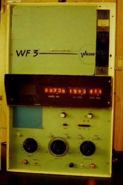 |
WF3 Operators console; Display/Indicators An 8 x 5cm CRT provided A/R & R scope displays; A/R scope of; 5,30,& 150km range, and a Rscan display of 1.5km for close in aquistion of the balloon borne target. Nixie tube digital indicators provided data readouts for Range, Azimuth and Elevation in the middle of the console . |
Performance specs
Range:150km max, better than 20m standard deviation
Angle: Better than 0.15° standard deviation
References
(1) A.L.West (private communication)