COMMUNICATION INTERFACE
 General
Description
General
Description
The Radar Data Communication Interface was developed in 1986.
An Alfatron A3000 Communications Interface was reprogrammed and relabeled
to provide a radar picture data storage and retransmission function
.
The original Alfatron A3000 was designed to be a buffer for serial data for
such applications as printers etc. This meant it was perfectly equipped to perform
an RS232 communications buffer function as it had serial ports as well as a
CPU and buffer ram.
Operation
The unit would receive synchronous serial radar
data (in the EEC binary format or the compressed Bureau version) and store that
data in its memory buffer. It would then retransmit the data in the compressed
Bureau synchronous format in reply to the request from an auto-answer modem.
It also would transmit the data out a separate channel in the Bureau asynchronous
ASCII format.
A later version added Baud rate select via switch settings and a 10 minute update mode that limited the output to transmitting only one picture every 10 minutes. The later was used to 'convert' RDRS transmitted data to appear like data from the Rapic Transmitters on the display systems. The continuos data from the RDRS would not been have presented as a resonable animated display.
Deployment
At some time RDCI units were deployed to the following radar and observational
sites;
Adelaide WF44, Adelaide RFC, Brisbane RFC, Brisbane RMC, Broome WF44, Cairns
WSO, Carnarvon WF100, Ceduna WF100, Charleville WF100, Eagle Farm WF44, Esperance
WF100, Geraldton WF100, Gladstone WF44, Hobart RFC, Laverton WF44 Head, Learmonth
WF44 Head, Mackay WF44, Melbourne RFC , Mildura WF100, Mt Gambier WF44, Mt Kanighan
WF44 Head, Perth WF100 (Kings Park), Perth RFC, Pt Hedland WF44, Pt Hedland
WSO, Mascot WF44, Sydney RFC, Tindal WF100, Tindal WSO, Townsville WF100, Townsville
WSO, Mt Stuart WF44, Weipa WF100, Williamtown WF44.
It is hard to assertain the number of units that existed, as they were moved
from obserational (Rapic Display) sites to radar sites when the dial-up network
changed from V26 bis toV22 bis modems.
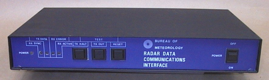
Construction
The unit was housed in a folded steel case, with three test switches and four
indicating LEDs on the front panel as well as the Power Switch. The rear panel
held the PCB mounted serial connectors and the DIP switches.